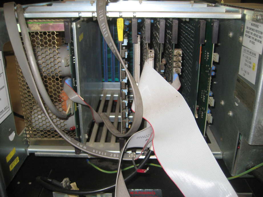
Some pictures of the MAI Basic Four 210 and 510 boards. You can show larger pictures by clicking on the picture.
This is the cabinet of the basic four 210, boards installed (from right to left) are:
Disk Controller board of the 210. This system was equiped with a 14" priam 6650-30 disk.
some PALs on the disk controller, patches as well ;-)
Eight Way Controller with 8 serial ports.
All port connectors are 8 pin connectors. Baud rate can be set by the dip switches, only one of the 8 switches must be set.
1: 9600, 2:4800, 3:2400, 4:1200, 5:600, 6:300, 7:150 and 8:110 Baud.
Memory board, based on AM9016, a 16kx1 dynamic RAM. This board has 128k of memory (with parity) installed.
This is exactly the same board that is installed in my 510 (same revision).
I assume the led is a parity error indicator and the switch is for resetting it.
It is connected to the 74S112 @ 2L (Pin 14=CLR). In the schematics the 112 is @4N and there is no switch but there is a power on reset for the flip flop.
So the schematics in the service manual are older than the boards i have.
The dip switch is set different on the 210, the 210 has 0011, the 510 is set as 1111.
This is the memory power supply board. The system is equiped with a backup battery that will supply power (and refresh for the DRAM's ?) to the memory board(s).
MTC controller based on a Z80 cpu.
Switching power Supply board of the 210.