Some pictures of the MAI Basic Four 210 and 510 CPU boards. You can show larger pictures by clicking on the picture.
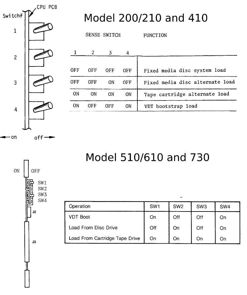
These are the supported switch functions, Tape and VDT (Terminal) boot are the same. Boot from disk is different for the 2xx/400. May be because the 510/610 an 730 are using external disk drives while the 2xx and 410 are equiped with 14" internal harddisks.
I have no documentation about the microcode of these cpus. However, i fould this "test" program in the service manual for the 210/400 systems, dont know if it works on the 510/600/730, these models do not have the 2 serial ports on the cpu aux board installed.
 Set the switches to VDT boot
 Set the terminal to half duplex
 Start the cpu using the "load" switch
 enter the following code and terminate the input with MB-IV. Do not enter the blanks!

   0200 0487 FFBF EFAF 4839 0097 D000 491A FD1F F500

 start it with the start address and IV

   0200

The running cpu should display:

   0123456789:; =?

17 Feb 2015
Today i tried the above test program on my system 210. The first time i tried the CPU state switched to hold while
i have entered the code. Tried a little bit and after entering 0..F the CPU no longer stopped after each key.
I entered the test and started it, it worked. That means the cpu board can execute some code.
However, tried it a second time and it did not work.
Seems to be i have to do more tests before i can start the system with the harddisk. (hoping that the disk will work)

This is the cpu board of my 210

This is the cpu aux board from my 210. At the top right you can see the microcode proms (512 bytes x 8 each). The 2 serial ports are implemented using the AY-5-1013.
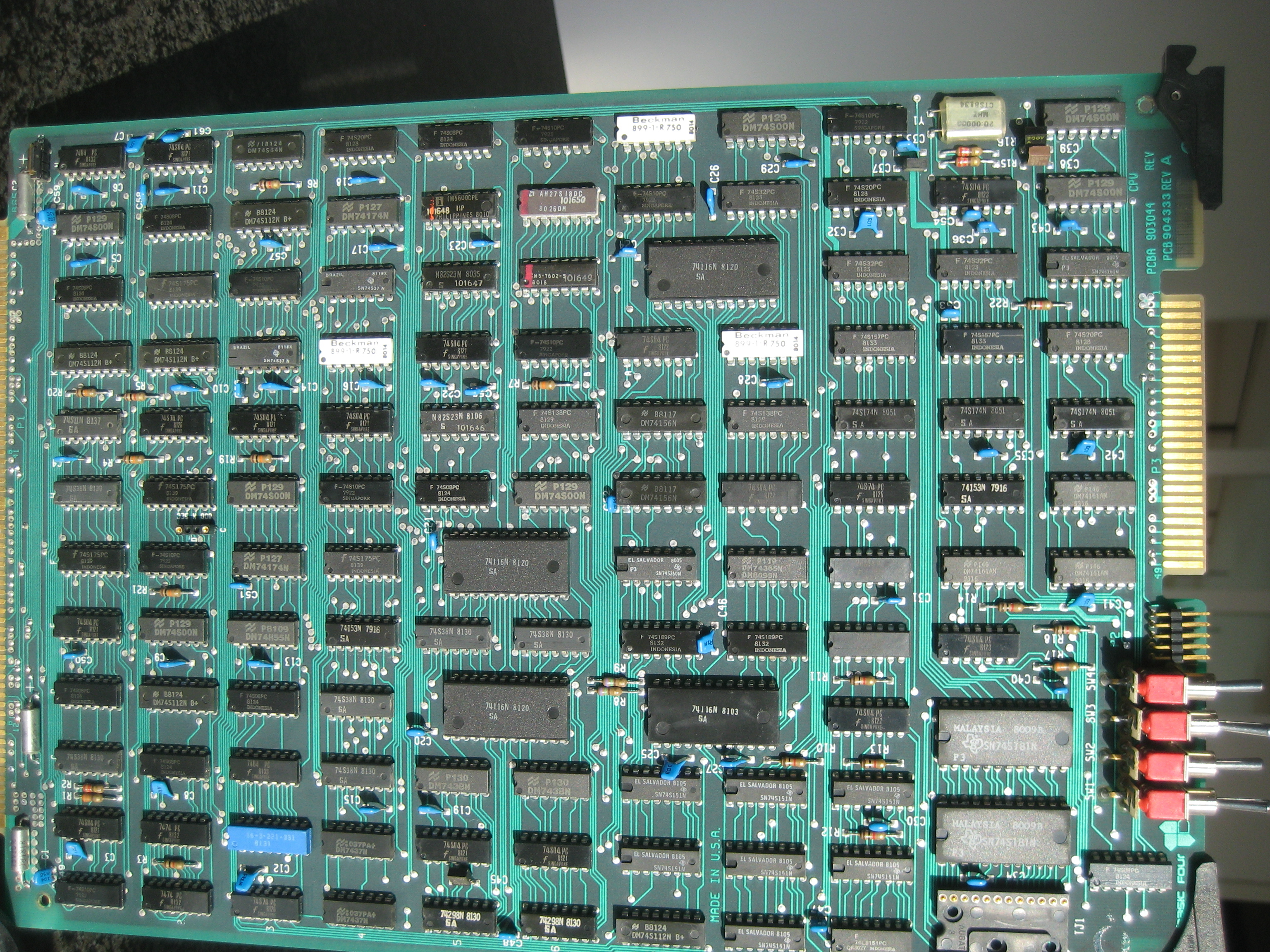
The cpu boards from my system 510. The board seem to be identical to the one from the model 210. The dip-switch settings for disk-boot are differnt than the ones for model 210.


This is what i have found for this jumper in the field information (FIB 00010 05/12/80)
*** 1300/1320/1340 CPU PCBA - 600/800 nanosecond jumper ***
PARTS ALERT
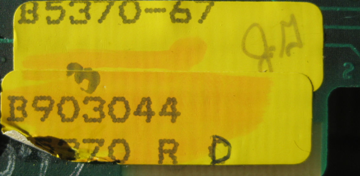
BFC #903044 (MM #820091) CPU PCB may be substituted on orders for:
BFC #901425 (MM #081003) 1300 CPU PCB
BFC #902140 (MM #820090) 1325/1345 CPU PCB
When using the PCB as a 1300, a jumper must be installed from Pins 1 to 4 of the socket located between IC's, 2F and 2H. This socket is marked 800 NSEC.
When using this PCB as a 1325/1345, the jumper is not needed but socket is marked 600 NSEC.
ORIGINATOR: G. JOHNSON

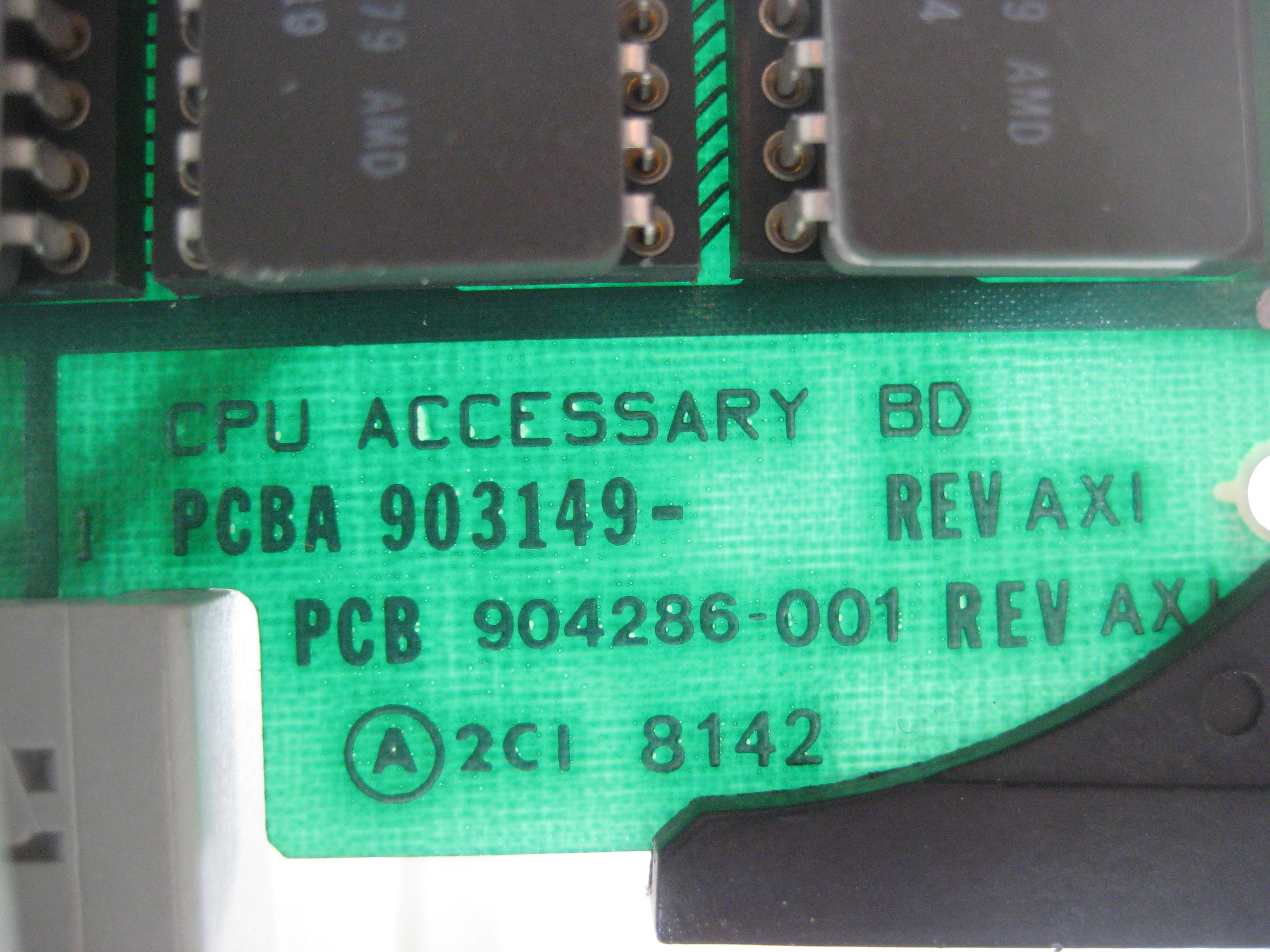
The aux-cpu board from the 510. It seems to be the same board again, however, the serial ports are not installed. The microcode proms
have the same numbers except Rom 3
165002-041 for the Model 510
165002-014 for the Model 210